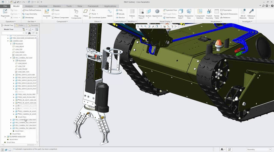
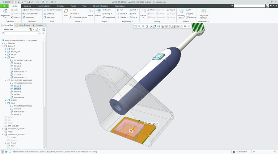
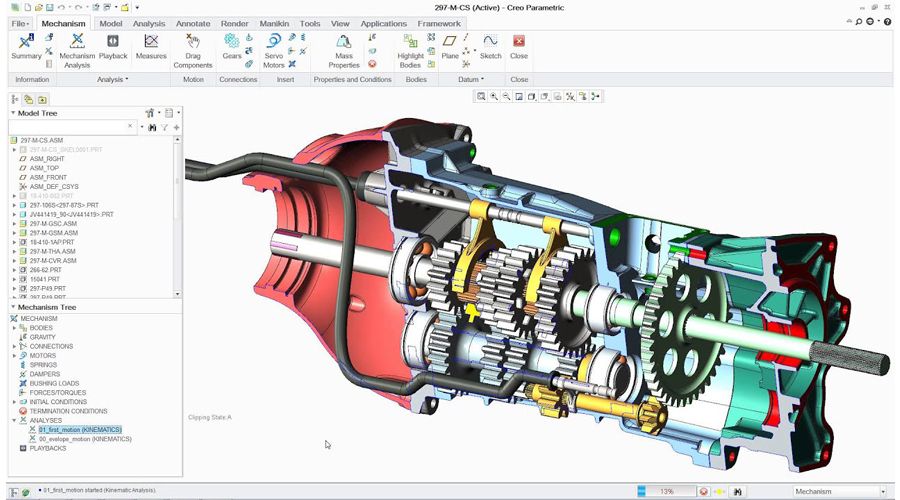
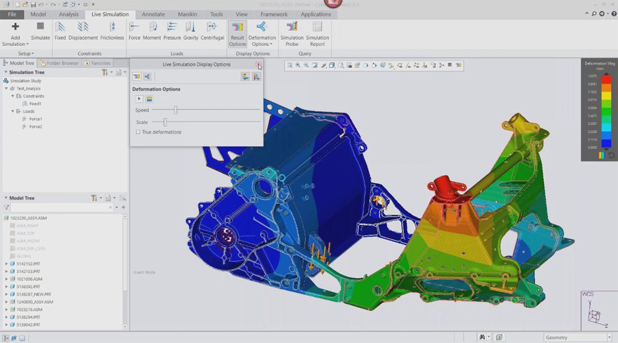
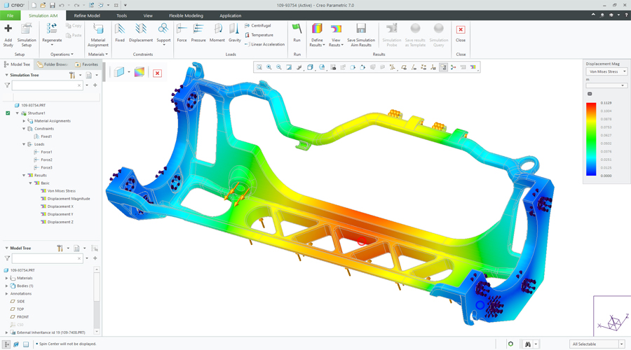
To streamline workflows using Model-based definition and to reduce time, errors and cost while also improve product quality.
- Introduction to Creo Parametric
- Feature-Based Nature
- Bidirectional Associative Property
- Parametric Nature
- System Requirements
- Getting Started with Creo Parametric
- Important Terms and Definitions
- File Menu Options
- Managing Files
- Menu Manager
- Model Tree
- Understanding the Functions of the Mouse Buttons
- Ribbon
- Toolbars
- Navigator
- Creo Parametric Browser
- Appearance Gallery
- Rendering in Creo Parametric
- Color Scheme Used in this Book
- The Sketch Mode
- Working with the Sketch Mode
- Invoking the Sketch Mode
- The Sketcher Environment
- Working with a Sketch in the Sketch Mode
- Drawing a Sketch Using tools available in the Sketch Tab
- Placing a Point
- Drawing a Line
- Drawing a Centerline
- Drawing a Geometry Centerline
- Drawing a Rectangle
- Drawing a Circle
- Drawing an Ellipse
- Drawing an Arc
- Dimensioning the Sketch
- Converting a Weak Dimension into a Strong Dimension
- Dimensioning a Sketch Using the Normal Tool
- Dimensioning the Basic Sketched Entities
- Linear Dimensioning of a Line
- Angular Dimensioning of an Arc
- Diameter Dimensioning
- Radial Dimensioning
- Dimensioning Revolved Sections
- Working with Constraints
- Types of Constraints
- Disabling Constraints
- Modifying the Dimensions of a Sketch
- Using the Modify Button
- Modifying a Dimension by Double-Clicking on it
- Modifying Dimensions Dynamically
- Resolve Sketch Dialog Box
- Deleting the Sketched Entities
- Trimming the Sketched Entities
- Mirroring the Sketched Entities
- Inserting Standard/User-Defined Sketches
- Drawing Display Options
- Dimensioning the Sketch
- Dimensioning a Sketch Using the Baseline Tool
- Replacing the Dimensions of a Sketch Using the Replace Tool
- Creating Fillets
- Creating Circular Fillets
- Creating Elliptical Fillets
- Creating a Reference Coordinate System
- Working with Splines
- Creating a Spline
- Dimensioning of Splines
- Modifying a Spline
- Writing Text in the Sketcher Environment
- Rotating and Resizing Entities
- Importing 2D Drawings in the Sketch Model
- Creating Base Features
- Invoking the Part Mode
- The Default Datum Planes
- Creating a Protrusion
- Extruding a Sketch
- Revolving a Sketch
- Understanding the Orientation of Datum Planes
- Parent-Child Relationship
- Implicit Relationship
- Explicit Relationship
- Nesting of Sketches
- Datums
- Default Datum Planes
- Need for Datums in Modeling
- Selection Method in Creo Parametric
- Datum Options
- Datum Planes
- Creating Datum Planes
- Datum Planes Created On-The-Fly
- Datum Axes
- Datum Points
- Creating Cuts
- Removing Material by Using the Extrude Tool
- Removing Material by Using the Revolve Tool
- Options Aiding Construction of Parts
- Creating Holes
- The Hole Dashboard
- Important Points to Remember While Creating a Hole
- Creating Rounds
- Creating Basic Rounds
- Creating a Variable Radius Round
- Points to Remember While Creating Rounds
- Creating Chamfers
- Corner Chamfer
- Edge Chamfer
- Understanding Ribs
- Creating Trajectory Ribs
- Creating Profile Ribs
- Editing Features of a Model
- Editing Definition or Redefining Features
- Reordering Features
- Rerouting Features
- Suppressing Features
- Deleting Features
- Modifying Features
Introduction
- Creating Feature Patterns
- Uses of patterns
- Creating Patterns
- Deleting a Pattern
- Copying Features
- New Refs
- Same Refs
- Mirror
- Move
- Select
- Mirroring a Geometry
- Creating a Section of a Solid Model
- Work Region Method
- Other Protrusion Options
- Sweep Features
- Creating Sweep Protrusions
- Aligning a Sketched Trajectory to an Existing Geometry
- Creating a Thin Sweep Protrusion
- Creating a Sweep Cut
- Blend Features
- Parallel Blend
- Rotational Blend
- General Blend
- Using Blend Vertex
- Shell Feature
- Creating a Constant Thickness Shell
- Creating a Variable Thickness Shell 8
- Datum Curves
- Creating a Datum Curve by Using the Curve Button
- Creating a Datum Curve by Sketching
- Creating a Curve by Using the Intersect Option
- Creating a Curve by Using the Project Option
- Creating a Curve by Using the Wrap Option
- Creating Draft Features
- Advanced Feature Creation Tools
- Variable Section Sweep Using the Sweep Option
- Swept Blend
- Helical Sweep
- Blend Section to Surfaces
- Blend Between Surfaces
- Advanced Modeling Tools
- Toroidal Bend
- Spinal Bend
- Warp
- Transform Tool
- Warp Tool
- Spine Tool
- Stretch Tool
- Bend Tool
- Twist Tool
- Sculpt Tool
- Assembly Modeling
- Important Terms Related to the Assembly Mode
- Top-down Approach
- Bottom-up Approach
- Placement Constraints
- Package
- Creating Top-down Assemblies
- Creating Components in the Assembly Mode
- Creating Bottom-up Assemblies
- Inserting Components in an Assembly
- Assembling Components
- Displaying Components in a Separate Window
- Displaying Components in the Same Window
- 3D Dragger
- Applying Constraints
- Status Area
- Placement Tab
- Move Tab
- Packaging Components
- Creating Simplified Representations
- Redefining the Components of an Assembly
- Reordering Components
- Suppressing/Resuming Components
- Replacing
- Assembling Repeated Copies of a Component
- Modifying the Components of an Assembly
- Modifying Dimensions of a Feature of a Component
- Redefining a Feature of a Component
- Creating the Exploded State
- References Tab Offset Tab
- Explode Line Tab
- The Bill of Materials
- Global Interference
- Pairs Clearance
- The Drawing Mode
- Generating Drawing Views
- Generating the General View
- Generating the Projection View
- Generating the Detailed View
- Generating the Auxiliary View
- Generating the Revolved Section View
- Generating the Copy and Align View
- Generating the 3D Cross-Section View
- Editing the Drawing Views
- Moving the Drawing View
- Erasing the Drawing View
- Deleting the Drawing View
- Adding New Parts or Assemblies to the Current Drawing
- Modifying the Drawing Views
- Changing the View Type
- Changing the View Scale
- Reorienting the Views
- Modifying the Cross-sections
- Modifying Boundaries of Views
- Adding or Removing the Cross-section Arrows
- Modifying the Perspective Views
- Modifying Other Parameters
- Editing the Cross-section Hatching
- Dimensioning the Drawing Views
- Show Model Annotations Dialog Box
- Adding Notes to the Drawing
- Adding Tolerances in the Drawing Views
- Dimensional Tolerances
- Geometric Tolerances
- Editing the Geometric Tolerances
- Adding Balloons to the Assembly Views
- Adding Reference Datums to the Drawing Views
- Modifying and Editing Dimensions
- Modifying the Dimensions Using the Dimension Properties Dialog Box
- Modifying the Drawing Items Using the Shortcut Menu
- Cleaning Up the Dimensions
- Sketching in the Drawing Mode
- Modifying the Sketched Entities
- User-Defined Drawing Formats
- Retrieving the User-Defined Formats in the Drawings
- Adding and Removing Sheets in the Drawing
- Creating Tables in the Drawing Mode
- Generating the BOM and Balloons in Drawings
- Surface Modeling
- Creating Surfaces in Creo Parametric
- Creating an Extruded Surface
- Creating a Revolved Surface
- Creating a Sweep Surface
- Creating a Blended Surface
- Creating a Swept Blend Surface
- Creating a Helical Sweep Surface
- Creating a Surface by Blending the Boundaries
- Creating a Variable Section Sweep Surface Using the Sweep Tool
- Creating Surfaces the Using the Style Environment of Creo Parametric
- Style Dashboard
- Surface Editing Tools
- Mirroring the Surfaces
- Merging the Surfaces
- Trimming the Surfaces
- Creating the Fill Surfaces
- Creating the Intersect Curves
- Creating the Offset Surfaces
- Adding Thickness to a Surface
- Converting a Surface into a Solid
- Creating a Round at the Vertex of a Surface
- Freestyle modelling environment
- Freestyle Dashboard
- Introduction to Sheet metal
- Invoking the Sheet metal Mode
- Introduction to Sheet metal Walls
- Creating the Planar Wall
- Creating the Unattached Revolve Wall
- Creating the Unattached Blend Wall
- Creating the Unattached Offset Wall
- Creating Reliefs in Sheet metal Components
- Creating a Flat Wall
- Creating a Twist Wall
- Creating an Extend Wall
- Creating a Flange Wall
- Creating the Bend Feature
- Creating the Unbend Feature
- Creating the Bend Back
- Conversion to Sheet metal Part
- Creating Cuts in the Sheet metal Components
We provide all kind of services like helping students to their college projects, assignments, preparation for exams and the corporate professionals also on to their company projects.
Caliber Training & Services – Start Your Creo Training Here!
You need a 3D CAD system like Creo to create better products faster. It is possible to study Creo from the early stages of product design through production and beyond with Creo training online from the best Pro E Training Institute near me.
New and exciting ways to integrate established functionality with cutting-edge technology like generative design and augmented reality. As well as using the Internet of Things (IoT) to increase product quality and speed up iterations. Only Creo provides the transformational tools you need to achieve a competitive edge and earn a market share in the fast-paced world of product development.
Thanks to Creo, it is possible to create using the most up-to-date technology.
Designed for the ever-evolving world of product design, Creo delivers on its promise to continual CAD innovation and offers powerful new technologies.
Creo capabilities
PTC developed Creo Parametric to provide a solid base upon which its customers build additional capabilities. Creo’s enhanced capabilities allow you to satisfy your needs even as your goods’ technical complexity increases.
Hence, our Creo Software online training in Ohio spans a range of subjects. Whether you are in Ohio or you are looking for a Creo online training course in Maryland, our classes are from basics up to the top. Offering the lessons online, using engaging tools, and allowing for carrying out practical projects, students will learn practical lessons and get in-depth knowledge of Creo’s functions.
Creo Training: Enroll, Learn, Achieve
Many modules are included in Autodesk Revit MEP Training near me to assist students in improving their knowledge of the technology and its many capabilities. Here are some of the modules:
Course Objectives
The Creo online training course in Maryland is offered to assist product designers and engineers in producing a virtual product design at Caliber Training & Services. Creo has all of the tools necessary to complete a product design project. Sketching, modeling, validation of design, and visualizing the product design will benefit from this Creo training online.
Creo E-Learning Courses
Creo eLearning offers students a high-level overview of the software’s features. E-Learning is the best option when it comes to learning about a product’s interface and functioning. There are no time constraints in eLearning.
Creo Tutorials
Free, on-demand tutorials are designed to help people overcome existing problems. They make it easier for Creo students to get over frequent roadblocks.
Creo Training Courses at Caliber Training & Services
With Creo course online near me, Caliber Training & Services, the CREO Trainer, will empower manufacturers, engineers, and designers to gain a different perspective by presenting new ways to think about and explore design iterations.
Learn with Creo Course Online
Our Creo course online offers the complete package in learning the Creo software and its features, ranging from the basic to the advanced level. It comes in handy for new users as well as those with prior experience of using the software.
Flexible Creo Training Online
With our Creo training online option, you can pick your dates, meaning you don’t have to wait for a specific time to start learning. No matter whether you are in Ohio, Maryland, or anywhere else, it is quite possible to attend our training at any point in time.
So, any engineering or design professional in Ohio who is seeking training in Creo software from Software can enroll in the industry-oriented training courses offered by our institute to hone skills that are relevant to the industry.
You will find our Creo online training course in Maryland which enables you to become proficient in the software so that you learn 3D design, parametric modeling, and simulation.
Expert-Led Instruction
Expert trainers are with you at every step, helping you understand the fundamental strengths and applications of product design and engineering.
Are You Interested in Creo Training?
We’re not teaching Creo; we’re teaching methods of seeing the world. With decades of expertise in engineering and design, our team is driven and experienced. We can provide innovative approaches to addressing challenges by going beyond the product itself. We can help you and your team learn fast and effectively by diving into design issues.
Being the best institute for Creo Software online training in Ohio, customized content is used in our Creo training sessions. The emphasis is on core-modeling abilities and putting design challenges into perspective about the manufacturing process. Caliber Training & Services may assist you or your team overcome software challenges, existing project design hurdles, or just pushing the boundaries of what you believed you were capable of.
As part of our workshops, we encourage mechanical engineers and product designers to expand and challenge their thinking, which results in the creation of new products and processes and the development of collaborative connections.
We are your Creo trainer near you. Contact Today!
FAQ
Indeed there is plenty that can be learned with Creo and there are websites that offer courses on Creo. Caliber Training & Services is the best provider of Creo Software online training in Ohio, which provides courses from scratch to advanced.
The cost of online Creo training can vary depending on the course, length, and any extra resources included. For the best information, please reach out to our admissions team. They can help you find a program that suits your needs and budget.
If you take a Creo online training course in Maryland, then it depends on you totally to become proficient, depending on your experience and choice of the course.

